
Introduction
Selecting the correct vibrating screen mesh size starts with the required separation size, not the mesh number alone. The actual screen aperture should match the target particle size, while wire diameter, material properties, moisture, bulk density and screening capacity also affect the final mesh specification.
This guide explains how to convert particle size to mesh size and how to select the correct screen opening for different materials and screening conditions.
What Is Vibrating Screen Mesh Size?
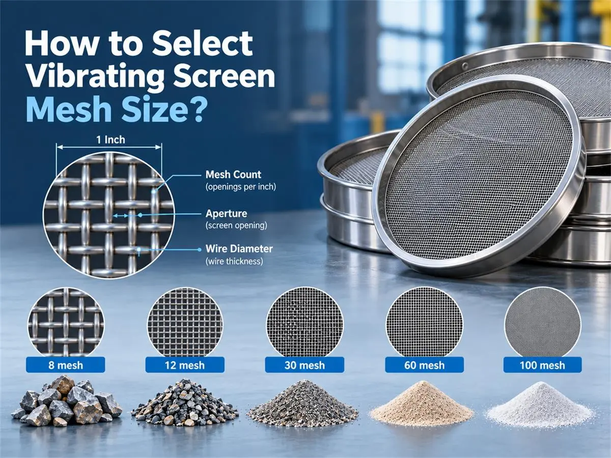
Vibrating screen mesh size defines the screening opening used to separate material by particle size. It is normally specified by mesh count, aperture size and wire diameter.
Mesh Count → Aperture → Particle Size
Mesh count indicates the number of openings per linear inch. In general, the higher the mesh number, the smaller the screen opening and the finer the separation.
However, mesh count does not directly equal aperture size. The actual clear opening is determined by both mesh count and wire diameter. Screens with the same mesh number can have different apertures when different wire diameters are used.
For industrial screening, aperture size in mm or μm should be the primary selection parameter, with wire diameter selected according to material characteristics, screening accuracy, capacity and screen strength requirements.
Mesh Size vs. Aperture vs. Particle Size
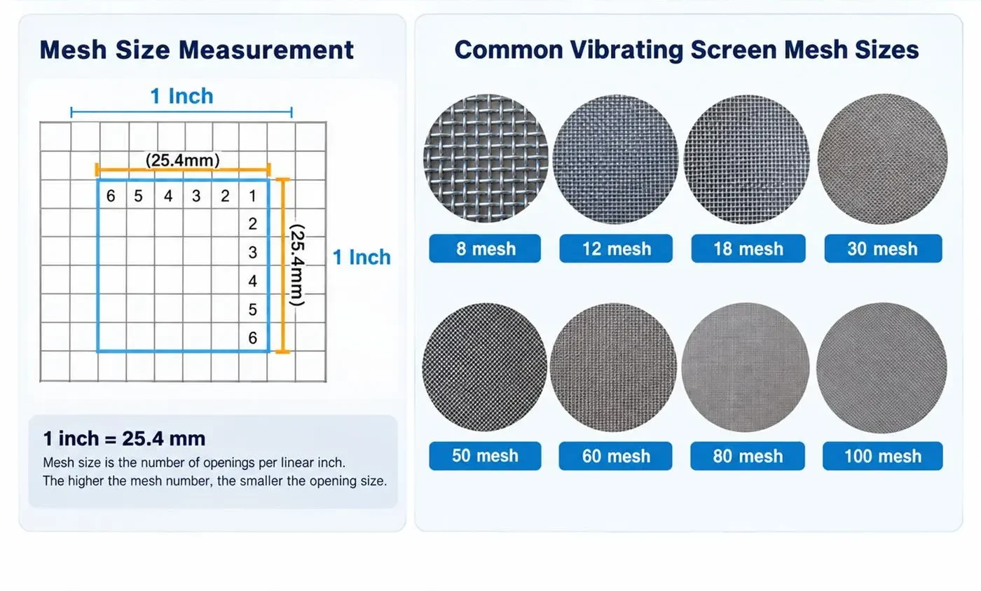
Mesh size, aperture and particle size are related, but they describe different parameters in screening.
Mesh size refers to the number of openings per linear inch of screen. Aperture is the actual clear opening between adjacent wires, usually specified in millimeters (mm) or microns (μm). Particle size refers to the size of the material being separated.
For screen selection, aperture is usually the more direct specification. Two screens with the same mesh count can have different aperture sizes if the wire diameter is different. A thicker wire provides greater strength and wear resistance but reduces the clear opening and open screening area.
| Parameter | Meaning | Common Unit | Selection Relevance |
| Mesh Size | Number of openings per linear inch | Mesh | General screen designation |
| Aperture | Clear opening between screen wires | mm / 渭m | Determines the nominal separation size |
| Particle Size | Size of the material being screened | mm / 渭m | Defines the required cut or product size |
| Wire Diameter | Thickness of the screen wire | mm | Affects aperture, strength and open area |
For accurate sizing, we recommend specifying the required particle cut size and actual screen aperture, rather than selecting the screen by mesh number alone. Feed size distribution, particle shape, moisture, screening capacity and acceptable oversize or undersize should also be considered before the final mesh specification is confirmed.
Vibrating Screen Mesh Size Chart
A vibrating screen mesh size chart provides a practical reference for converting mesh count to approximate aperture size in microns (μm) and millimeters (mm). As the mesh number increases, the screen opening becomes smaller and the material separation becomes finer.
For industrial screening, mesh count should be used as a reference rather than the only selection parameter. The actual aperture, wire diameter and required particle cut size should be confirmed when specifying a screen.
Mesh to Micron and Millimeter Conversion
The table below shows commonly used mesh sizes and their approximate opening sizes.
| Mesh Size | Approx. Aperture (μm) | Approx. Aperture (mm) | Screening Range |
| 4 mesh | 4,750 μm | 4.75 mm | Coarse particles |
| 6 mesh | 3,350 μm | 3.35 mm | Coarse particles |
| 8 mesh | 2,360 μm | 2.36 mm | Coarse particles |
| 10 mesh | 2,000 μm | 2.00 mm | Coarse screening |
| 12 mesh | 1,700 μm | 1.70 mm | Coarse screening |
| 16 mesh | 1,180 μm | 1.18 mm | Granular materials |
| 20 mesh | 850 μm | 0.850 mm | Granular materials |
| 30 mesh | 600 μm | 0.600 mm | Medium screening |
| 40 mesh | 425 μm | 0.425 mm | Medium-fine screening |
| 50 mesh | 300 μm | 0.300 mm | Fine screening |
| 60 mesh | 250 μm | 0.250 mm | Fine screening |
| 80 mesh | 180 μm | 0.180 mm | Fine screening |
| 100 mesh | 150 μm | 0.150 mm | Fine powder |
| 120 mesh | 125 μm | 0.125 mm | Fine powder |
| 140 mesh | 106 μm | 0.106 mm | Fine powder |
| 170 mesh | 90 μm | 0.090 mm | Fine powder |
| 200 mesh | 75 μm | 0.075 mm | Very fine powder |
| 230 mesh | 63 μm | 0.063 mm | Very fine powder |
| 270 mesh | 53 μm | 0.053 mm | Very fine powder |
| 325 mesh | 45 μm | 0.045 mm | Ultra-fine screening |
| 400 mesh | 38 μm | 0.038 mm | Ultra-fine screening |
Note: The values above are reference openings commonly used for mesh-to-micron conversion. Actual screen aperture can vary with wire diameter, weave type and screen standard. For precision classification, specify the required aperture in mm or μm and confirm the screen construction before production.
How to Read the Mesh Size Chart?
The relationship is straightforward: a higher mesh number generally means a smaller opening and finer separation. For example, 40 mesh corresponds to an opening of approximately 425 μm, while 100 mesh is approximately 150 μm and 200 mesh approximately 75 μm.
However, the closest mesh value should not automatically be treated as the final screen specification. For industrial vibrating screens, the selection should also consider particle size distribution, required cut point, material shape, moisture, throughput and acceptable screening efficiency. For difficult fine powders, mesh blinding and material passage through the opening should also be evaluated.
How to Select the Right Vibrating Screen Mesh Size?
Selecting vibrating screen mesh starts with the required separation size, then checks whether the screen opening, wire construction and screening conditions can achieve that cut consistently. Mesh count alone is not enough for an industrial screening specification.
For a new project, we normally review the feed particle size, target product size, material characteristics, required capacity and screening accuracy before confirming the final mesh.
Step 1 — Define the Required Separation Size
First determine what size needs to pass through the screen and what size must remain above it. This establishes the required cut size and provides the basis for selecting the screen aperture.
For multi-deck screening, define each required product fraction separately.
For example:
- Feed: 0–2 mm
- Required fractions: 0–0.5 mm / 0.5–1.0 mm / 1.0–2.0 mm
In this case, the screen openings should be selected around the required 0.5 mm and 1.0 mm separation points, then verified against the actual particle size distribution and screening performance.
Step 2 — Match Particle Size with Screen Aperture
Convert the required cut size into millimeters (mm) or microns (μm) and use the mesh chart to identify the corresponding mesh range.
| equired Cut Size | Approx. Reference Mesh | Selection Basis |
| 2.00 mm | 10 mesh | Coarse classification |
| 0.85 mm | 20 mesh | Granular material sizing |
| 0.425 mm | 40 mesh | Medium-fine classification |
| 0.250 mm | 60 mesh | Fine screening |
| 0.150 mm | 100 mesh | Fine powder classification |
| 0.075 mm | 200 mesh | Very fine screening |
| 0.045 mm | 325 mesh | Ultra-fine screening |
These values are selection references. Actual aperture should be confirmed rather than specifying mesh count alone, especially where particle-size tolerance is critical.
Step 3 — Check the Material Characteristics
The same aperture can perform differently with different materials. Before the mesh is finalized, consider how the material behaves on the screen surface.
Dry, free-flowing particles generally pass through the aperture more easily. Wet or sticky materials have a higher risk of blinding. Irregular or elongated particles may pass differently from near-spherical particles, while abrasive materials place greater demands on wire strength and wear resistance.
For fine powders, also check agglomeration, static electricity and moisture, as these factors can significantly reduce effective screening capacity.
Step 4 — Select Wire Diameter and Screen Material
Wire diameter affects both the strength of the mesh and its open screening area. A thicker wire improves wear resistance and service life but reduces the clear opening area. A thinner wire provides more open area and can improve material passage, but may have lower mechanical strength.
Screen material should also match the process:
| Screen Material | Typical Selection Consideration |
| SS304 | General industrial, food and chemical screening |
| SS316L | Higher corrosion resistance and hygiene requirements |
| Carbon Steel | General mineral and non-corrosive material screening |
| Wear-Resistant Mesh | Abrasive minerals, sand and continuous-duty applications |
The final specification should balance aperture accuracy, open area, wear resistance and screen life.
Step 5 — Verify Capacity and Screening Performance
The correct aperture does not automatically guarantee the required production capacity. Actual screening performance also depends on feed rate, bulk density, moisture, particle size distribution, screen area and the percentage of near-size particles.
Materials containing a high proportion of particles close to the screen opening are generally more difficult to separate and may require additional screen area or anti-blinding measures.
For critical fine screening or high-capacity projects, we recommend confirming the mesh specification through material testing before the equipment configuration is finalized. This allows the screen aperture, deck arrangement and screening me
Recommended Mesh Sizes for Different Materials
Screen mesh size is determined by the required product size and separation duty, not by material name alone. The same material may use very different screen openings for scalping, grading, fine classification or powder removal.
The ranges below are practical references for common screening applications. Final selection should be based on the required cut size, particle size distribution, capacity and material behavior.
| Material / Application | Reference Mesh Range | Approx. Opening Range | Main Selection Consideration |
| Quartz / Silica Sand | 10–140 mesh | 2.00 mm–106 μm | Product grading, abrasion, capacity |
| Frac Sand / Proppant | 20–140 mesh | 850–106 μm | Defined product fractions, screening accuracy |
| Flour & Food Powders | 20–120 mesh | 850–125 μm | Product specification, hygiene, blinding |
| Chemical Powders | 40–200 mesh | 425–75 μm | Particle distribution, agglomeration, contamination control |
| Mineral Powders | 20–200 mesh | 850–75 μm | Abrasion, bulk density, throughput |
| Fine Industrial Powders | 100–325 mesh | 150–45 μm | Blinding, static buildup, fine-particle passage |
Reference ranges are for preliminary selection only. Actual screen aperture and mesh construction should be confirmed against the required finished-product specification.
Quartz Sand and Silica Sand
Quartz and silica sand screening commonly covers coarse grading through fine classification. Depending on the finished product, screen openings may range from approximately 2.0 mm down to 106 μm (10–140 mesh).
For multi-size production, each deck should be selected according to the required fraction rather than using one general mesh specification. Abrasive wear is also important. Sanyuantang recommends checking wire diameter, open area and screen life together with the required cut size, particularly on continuous high-capacity lines.
Frac Sand and Proppant
Frac sand and ceramic proppant require controlled particle-size fractions such as 20/40, 30/50, 40/70 and 70/140 mesh. In these applications, the numbers describe the required product grading range and should not be treated as a single screen specification.
A production line normally uses multiple screening decks to separate the feed into specified fractions. Screen configuration should follow the required grading standard, feed distribution and throughput. For high-capacity frac sand projects, Sanyuantang also checks the effective screening area and near-size particle loading before the deck configuration is confirmed.
Flour and Food Powders
Food screening can range from coarse impurity removal to fine powder classification. A reference range of approximately 20–120 mesh (850–125 μm) covers many flour, starch and powdered-food applications, but the final aperture should follow the product specification.
For food-contact screening, mesh material, surface condition and cleanability are as important as opening size. SS304 or SS316L may be selected according to hygiene and corrosion requirements. Fine or moisture-sensitive powders should also be checked for screen blinding.
Chemical Powders
Chemical powders often require finer classification, typically within a broad reference range of 40–200 mesh (425–75 μm). Actual selection depends strongly on particle distribution, flowability, moisture, agglomeration and contamination requirements.
When conventional mesh shows poor material passage, simply increasing the mesh number is not the solution. The screening method may also need to be reviewed. For difficult fine powders, ultrasonic assistance or other anti-blinding measures can be considered after material testing.
Minerals and Abrasive Materials
Mineral powders, garnet, emery and other abrasive materials may use openings from approximately 850 μm to 75 μm (20–200 mesh) depending on the required product grade.
For these materials, screen wear can directly affect aperture accuracy and product consistency. We recommend balancing wire strength, open area, wear resistance and screening capacity rather than selecting the thinnest possible wire for higher open area.
Fine Industrial Powders
For powders below approximately 150 μm, screening becomes increasingly sensitive to particle shape, moisture, static electricity and agglomeration. Applications in the 100–325 mesh range (150–45 μm) therefore require more than a simple mesh conversion.
Sanyuantang normally recommends a material test when fine powder must be separated at high accuracy or stable throughput. Test results can be used to confirm the actual aperture, screening method, effective screen area and anti-blinding configuration before the equipment is finalized.
Contact Us
Get the Right Mesh for Your Screening Process
Not sure which mesh size or screen opening fits your material? Send Sanyuantang your material, feed size, required product size and capacity. We can review the screening duty and recommend a suitable mesh, screen configuration and equipment solution.
Response within one business day
How Material Properties Affect Mesh Selection?
Particle size is only the starting point for mesh selection. Materials with the same nominal particle size can behave very differently on a vibrating screen. Moisture, particle shape, bulk density, abrasiveness, flowability and static electricity all affect how easily particles reach and pass through the screen opening.
For this reason, Sanyuantang recommends evaluating the material condition together with the required cut size. For difficult materials, the correct solution may involve changing the wire diameter, open area, screening motion or anti-blinding method, rather than simply changing to a larger or smaller mesh.
Wet or Sticky Materials
Moisture can cause fine particles to adhere to each other and to the screen surface. Sticky material may gradually cover the openings, reducing effective screening area and causing mesh blinding or clogging.
For wet or cohesive feed, consider:
Actual moisture content and whether it changes during production
Percentage of fines in the feed
Tendency to agglomerate or coat the screen surface
Required capacity and acceptable screening efficiency
A slightly larger opening alone may not solve the problem. The screening method and anti-blinding arrangement should also be reviewed.
Abrasive Materials
Quartz sand, silica sand, garnet, emery and many mineral products can cause continuous wear on the screen surface.
For abrasive applications, mesh selection should balance aperture accuracy, wire diameter, open area and service life. Very thin wire may provide more open area, but it can wear faster under continuous high-capacity operation. Once the wire wears or breaks, product sizing accuracy can no longer be maintained.
Sanyuantang normally evaluates screen construction together with operating hours and feed rate when configuring abrasive-material screening lines.
Lightweight and Low-Density Powders
Light powders do not always contact the screen surface effectively. Excessive vibration or airflow can keep particles suspended above the mesh, reducing the probability of passing through the opening.
In these applications, screen area and machine operating parameters can be as important as the mesh itself. The objective is to maintain a controlled material layer and sufficient contact with the screening surface.
Irregular or Elongated Particles
Mesh conversion charts are based on opening size, but real particles are rarely perfectly spherical. Flakes, needles and irregular particles may pass through an aperture in one orientation but remain above the screen in another.
Where particle shape varies significantly, selection should be based on actual screening results and acceptable finished-product distribution, rather than nominal particle diameter alone.
Fine Powders with Static Electricity
Fine, dry powders can develop static electricity during conveying and screening. Particles may adhere to each other or to the mesh, particularly as the required separation becomes finer.
For fine screening, check:
Particle size → Moisture → Flowability → Agglomeration → Static behavior
If conventional vibration cannot keep the mesh open, an ultrasonic screening system may be considered to reduce blinding and improve fine-particle passage.
High Proportion of Near-Size Particles
A feed containing many particles close to the screen aperture is generally more difficult to separate. These near-size particles require more opportunities to reach the opening in the correct orientation and may remain on the screen longer.
For example, a 0.50 mm aperture will normally handle a feed containing mostly 1–2 mm particles more easily than a feed concentrated around 0.45–0.60 mm.
In this condition, Sanyuantang recommends checking feed distribution, screen area, bed depth and required throughput before the final mesh and equipment configuration are confirmed.
Engineering Note: If the material is wet, sticky, highly abrasive, irregularly shaped or finer than conventional screening can handle reliably, send us a material sample or particle-size distribution. A screening test provides a more reliable basis for mesh and equipment selection than mesh count alone.
When Do You Need Ultrasonic Screening?
Ultrasonic screening is used when conventional vibration cannot keep fine powder moving effectively through the screen openings. The decision should be based on material behavior and screening performance, not on mesh number alone.
Ultrasonic assistance should be considered when the material shows:
- Persistent mesh blinding — fine particles repeatedly block the screen openings.
- Agglomeration — powder forms small clusters that do not pass through the expected aperture.
- Static buildup — dry particles adhere to the mesh or to each other.
- Poor fine-particle passage — the required aperture is correct, but screening capacity remains low.
- Difficult near-size separation — a high proportion of particles are close to the required cut size.
An ultrasonic system applies high-frequency energy to the screen surface while the main screening machine provides the primary material movement. This helps reduce particle adhesion and keeps more openings available for screening.
A fine mesh does not automatically require ultrasonic assistance. Some free-flowing powders can be screened efficiently at small apertures using conventional vibration. Sanyuantang normally checks the particle size distribution, bulk density, moisture, flowability, required capacity and actual blinding condition before recommending an ultrasonic configuration.
For difficult fine powders, a material screening test is the preferred way to verify whether ultrasonic assistance provides a measurable improvement.
Common Vibrating Screen Mesh Selection Mistakes
Incorrect mesh selection can reduce capacity, increase screen wear or produce an inconsistent particle-size distribution. Most problems are caused by treating mesh count as an isolated parameter rather than part of the complete screening process.
1. Choosing by Mesh Number Only
Mesh count does not fully define a screen. The same mesh count can have different openings when wire diameter or weave construction changes. For precision sizing, confirm the actual aperture in mm or μm together with the mesh number.
2. Ignoring the Actual Aperture
The aperture determines which particles can physically pass through the screen. Selecting a nominal mesh without checking the clear opening can result in an incorrect cut size, particularly when the finished product has a narrow particle-size specification.
3. Using Wire That Is Too Thick
Thicker wire improves mechanical strength and wear resistance, but it also reduces open area. If the wire is unnecessarily heavy, less screening area is available for material passage, which can reduce capacity. Wire diameter should balance strength, open area and service life.
4. Ignoring Material Moisture
A mesh that performs well with dry material may blind rapidly when moisture increases. Fine particles can agglomerate or adhere to the wire, reducing effective screen area. Moisture and material flowability should therefore be confirmed under actual production conditions.
5. Selecting Mesh Without Considering Capacity
A correct aperture does not guarantee the required throughput. Feed rate, bulk density, percentage of near-size particles, screen area and number of separations all affect capacity. For production equipment, the mesh and machine configuration should be evaluated together.
What Information Do We Need to Recommend Screen Mesh?
To recommend a suitable mesh and screening configuration, Sanyuantang normally reviews the material, feed particle size, required product fractions, capacity and operating condition together. The more complete the process data, the more accurately we can determine the aperture, screen construction and equipment configuration.
For a new screening project, please provide the following information:
| Project Data | Example | Why We Need It |
| Material | Quartz sand | Determines flow, abrasion and screening characteristics |
| Feed Size | 0–5 mm | Defines the incoming particle-size range |
| Required Product Size | 20/40, 40/70 mesh | Determines the required separation points |
| Capacity | 15 t/h | Used to calculate required screening area |
| Moisture | <0.5% | Helps assess blinding and material flow |
| Number of Fractions | 3 | Determines the number of screening stages or decks |
| Bulk Density | 1.5 t/m³ | Supports capacity and material-loading calculations |
| Operating Hours | 16 h/day | Helps evaluate screen wear and duty requirements |
| Special Requirements | Low dust / food grade / corrosion resistance | Determines material and equipment configuration |
For multi-size products such as frac sand, please provide the complete required grading specification, rather than only one mesh number. We can then review the separation points, deck arrangement and effective screening area as one system.
Not sure which mesh to use? Send us your material data, particle-size requirement and target capacity. Sanyuantang can recommend the screen aperture and equipment configuration based on your actual screening duty.
FAQs About Vibrating Screen Mesh Size
How do I choose the right vibrating screen mesh size?
Start with the required particle cut size, then match it to the actual screen aperture. We also check feed size distribution, moisture, bulk density, particle shape and required capacity before confirming the mesh. For production screening, Sanyuantang recommends specifying the aperture in mm or μm, rather than relying on mesh count alone.
What mesh size do I need for my particle size?
Match the required particle cut size to the corresponding screen opening. As a reference, 40 mesh is about 425 μm, 100 mesh about 150 μm, and 200 mesh about 75 μm. These are nominal conversion values. We recommend confirming the actual aperture, wire diameter and particle-size distribution before selecting the final screen.
What is the difference between mesh size and aperture?
Mesh size indicates the number of openings per linear inch, while aperture is the clear opening between adjacent wires, measured in mm or μm. For example, 100 mesh is commonly associated with an opening of approximately 150 μm. In practical screening, we use actual aperture as the more direct reference for particle separation.
Does a higher mesh number mean a finer screen?
Yes. In standard woven wire mesh, a higher mesh number generally means more openings per inch and therefore a smaller aperture. For example, 40 mesh is approximately 425 μm, while 200 mesh is approximately 75 μm. However, mesh count alone does not define the exact opening because wire diameter also affects the available aperture.
How do you convert mesh size to microns?
Mesh-to-micron conversion is normally made using a standard reference chart rather than a single universal formula. For example, 60 mesh ≈ 250 μm, 100 mesh ≈ 150 μm, 200 mesh ≈ 75 μm, and 325 mesh ≈ 45 μm. We recommend using these values for preliminary selection and confirming the actual screen opening before production.
Can two screens with the same mesh size have different openings?
Yes. Two screens can have the same mesh count but different apertures if their wire diameters are different. A thicker wire reduces the clear opening and open screening area, while a thinner wire provides a larger opening. For accurate classification, we recommend specifying mesh count, aperture and wire diameter together when confirming the screen specification.
What mesh size is used for sand screening?
There is no single mesh size for sand screening. Quartz and silica sand may use openings from approximately 2.0 mm to 106 μm (10–140 mesh) depending on the required grade. Frac sand commonly uses product classifications such as 20/40, 30/50, 40/70 and 70/140 mesh. We select each screen deck according to the required finished fractions.
What causes vibrating screen mesh to clog?
Mesh clogging is commonly caused by moisture, sticky particles, agglomeration, near-size particles or static buildup in fine powders. Irregular particles can also lodge in the openings. We first check the material condition and particle-size distribution; if conventional vibration cannot keep fine mesh open, anti-blinding measures or ultrasonic screening may be considered.
Need a Screening or Material Handling Solution?
Tell us your material, particle size, required capacity and process requirements. Sanyuantang can recommend suitable screening, conveying and feeding equipment, or configure a complete material handling line for your project.